China OEM Zinc Alloy Parts Design Factories - How to design plastic parts – Mestech
Short Description:
China OEM Zinc Alloy Parts Design Factories - How to design plastic parts – Mestech Detail:
Product manufacturing starts with design. The design of plastic parts directly determines the realization of the internal structure, cost and function of the product, and also determines the next step of mold production, cost and cycle, as well as the injection molding and post-processing process and cost.
Plastic parts are widely used in various products, facilities and people’s lives in modern society. Plastic parts require different shapes and functions. They use plastic materials and their properties are varied. At the same time, there are many ways to make plastic parts in industry. So to design plastic parts is not a simple job.
Different part design and material is produced different processing. The processing for molding plastic mainly includes below:
1.injection molding
2.blowing molding
3.compression molding
4.rotational molding
5.thermoforming
6.extrusion
7.fabrication
8.foaming
There are numerous ways to mass produce them. Injection moulding is popular manufacturing method ,because injection molded 50%~60% plastic parts are produced byb injection molding, it is a high-speed production capability.
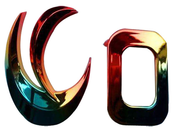
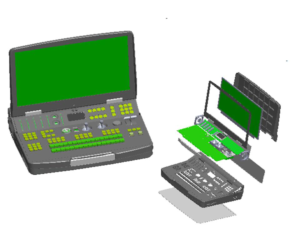
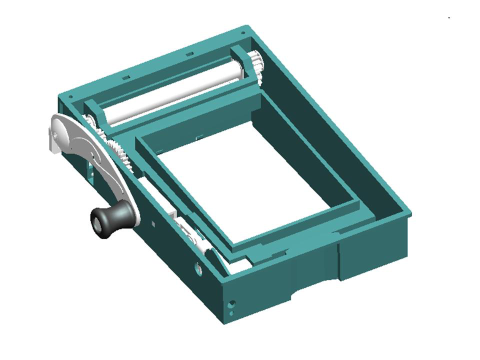
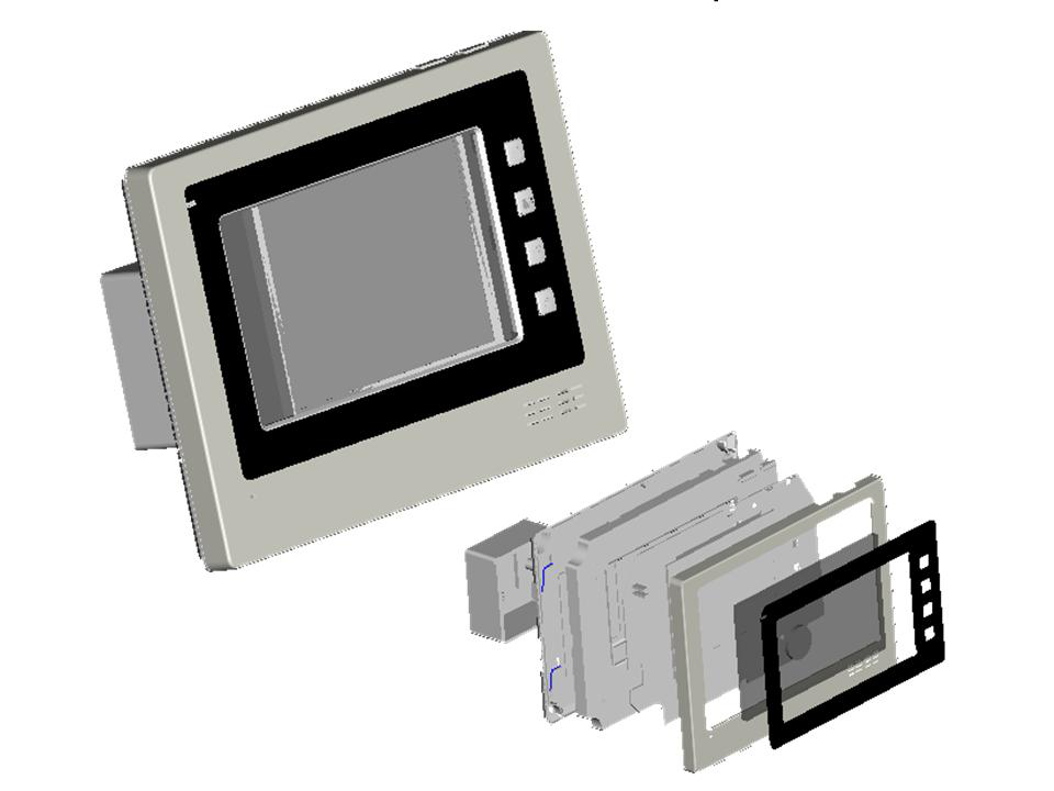
Show case for some plastic parts we designed:
Below we share detail how to design plastic parts in three aspects
*10 tips for design plastic parts you must know
1.Determine appearance design and size of the product.
This is the first step in the whole design process. According to market research and customer requirements, determine the appearance and function of products, and formulate product development tasks.
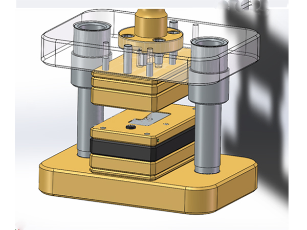
According to the development task, the development team carries on the technical and technological feasibility analysis to the product, and build the 3D appearance model of the product. Then, according to function realization and product assembly, possible parts are planned.
2.Separate individual parts from product drawings, choose plastic resin type for plastic parts
This step is to separate the parts from the 3D model obtained in the previous step and design them as individual. According to the functional requirements of the parts, choose suitable plastic raw materials or hardware materials. For example, ABS is usually used in the
shell, ABS/BC or PC is required to have certain mechanical properties, transparent parts such as lampshade, lamp post PMMA or PC, gear or wear parts POM or Nylon.
After selecting the material of the parts, the detail design can be started.
3.Define draft angles
Draft angles allow for removal of the plastic from the mold. Without draft angles, the part would offer significant resistance due to friction during removal. Draft angles should be present on the inside and the outside of the part. The deeper the part, the larger the draft angle. A simple rule of thumb is to have a 1 degree draft angle per inch. Not having enough draft angle may result in scrapes along the sides of the part and/or large ejector pin marks (more on this later).
Draft angles of outside surface: The deeper the part, the larger the draft angle. A simple rule of thumb is to have a 1 degree draft angle per inch. Not having enough draft angle may result in scrapes along the sides of the part and/or large ejector pin marks (more on this later).
Usually, in order to have good look surface, texture is made on the surface of parts. The wall with texture is rough, friction is large, and it is not easy to remove it from the cavity, so it requires a larger drawing angle. The coarser texture is, the bigger drafting angle needed.
4.Define wall thickness/uniform thickness
Solid shape moulding is not desired in injection moulding due to following reasons:
1).Cooling time is proportional to square of wall thickness. Long cooling time for solid will defeat the economy of mass production. (poor conductor of heat)
2).Thicker section shrink more than thinner section, thereby introduce differential shrinkage resulting in warpage or sink mark etc. (shrinkage characteristics of plastics and pvT characteristics)
Therefore we have basic rule for plastic part design; as far as possible wall thickness should be uniform or constant through out the part. This wall thickness is called nominal wall thickness.
If there is any solid section in the part, it should be made hollow by introducing core. This should ensure uniform wall thickness around the core.
3).What are the considerations for deciding wall thickness?
It must be thick and stiff enough for the job. Wall thickness could be 0.5 to 5mm.
It must also be thin enough to cool faster, resulting lower part weight and higher productivity.
Any variation in wall thickness should be kept as minimum as possible.
A plastic part with varying wall thickness will experience differing cooling rates and different shrinkage. In such case achieving close tolerance becomes very difficult and many times impossible. Where wall thickness variation is essential, the transition between the two should be gradual.
5.Connection design between parts
Usually we need to connect two shells together. To form an enclosed room between them to place the internal components ( PCB assembly or mechanism).
The usual types of connection:
1). Snap hooks:
Snap hooks connection is commonly used in small and medium size products. Its characteristic is that snap hooks is generally set at the edge of the parts, and the product size can be made smaller. When assembled, it is closed directly without using any tools such as screwdriver, ultrasonic welding die and others. The disadvantage is that the snap hooks may cause mold more complicated. The slider mechanism and lifter mechanism are needed to realize the snap hooks connection and increase the mold cost.
2). Screw joints:
Screw joints is firm and reliable. In particular, the screw + nut fixation is very reliable and durable, allowing multiple disassemblies without cracks. The screw connection is suitable for products with large locking force and multiple dismantling. The disadvantage is that the screw column takes up more space.
3). Mounting bosses:
Mounting bosses connection is to fix two parts by the tight coordination between the bosses and the holes. This way of connection is not strong enough to allow disassemble products. The disadvantage is that the locking strength will decrease as the time of disassembly increases.
4). Ultrasonic welding:
Ultrasonic welding is by putting the two parts into the ultrasonic mold and fusing the contact surface under the action of ultrasonic welding machine. The product size can be smaller, the injection mold is relatively simple, and the connection is firm. The disadvantage is the use of ultrasonic mold and ultrasonic welding machine, the product size can not be too large. After dismantling, the ultrasonic parts can not be used again.
6.Undercuts
Undercuts are items that interfere with the removal of either half of the mold. Undercuts can appear just about anywhere in the design. These are just as unacceptable, if not worse than a lack of a draft angle on the part. However, some undercuts are necessary and/or unavoidable. In those instances, necessary
undercuts are produced by sliding/moving parts in the mold.
Keep in mind that creating undercuts is more costly when producing the mold and should be kept to a minimum.
7.Support Ribs/ Gussets
Ribs in plastic part improve stiffness (relationship between load and part deflection) of the part and increases rigidity. It also enhances mould-ability as they hasten melt flow in the direction of the rib.
Ribs are placed along the direction of maximum stress and deflection on non-appearance surfaces of the part. Mould filling, shrinkage and ejection should also influence rib placement decisions.
Ribs that do not join with vertical wall should not end abruptly. Gradual transition to nominal wall should reduce the risk for stress concentration.
Rib – dimensions
Ribs should have following dimensions.
Rib thickness should be between 0.5 to 0.6 times nominal wall thickness to avoid sink mark.
Rib height should be 2.5 to 3 times nominal wall thickness.
Rib should have 0.5 to 1.5-degree draft angle to facilitate ejection.
Rib base should have radius 0.25 to 0.4 times nominal wall thickness.
Distance between two ribs should be 2 to 3 times (or more) nominal wall thickness.
8.Radiused Edges
When two surfaces meet, it forms a corner. At corner, wall thickness increases to 1.4 times the nominal wall thickness. This results in differential shrinkage and moulded-in stress and longer cooling time. Therefore, risk of failure in service increases at sharp corners.
To solve this problem, the corners should be smoothened with radius. Radius should be provided externally as well as internally. Never have internal sharp corner as it promotes crack. Radius should be such that they confirm to constant wall thickness rule. It is preferable to have radius of 0.6 to 0.75 times wall thickness at the corners. Never have internal sharp corner as it promotes crack.
9.Screw boss design
We always use screws to fix two half cases together, or fasten PCBA or other components onto the plastic parts. So screw bosses are the structure for screwing into and fixed parts.
The screw boss is cylindrical in shape. The boss may be linked at base with the mother part or it may be linked at side. Linking on side may results in thick section of plastic, which is not desirable as it can cause sink mark and increase cooling time. This problem can be solved by linking boss through a rib to the side wall as shown in the sketch. Boss can be made rigid by providing buttress ribs.
Screw is used on the boss to fasten some other part. There are thread forming type of screws and tread cutting type of screws. Thread forming screws are used on thermoplastics and thread cutting screws are used on inelastic thermoset plastic parts.
Thread forming screws produce female threads on internal wall of boss by cold flow – plastic is locally deformed rather than cut.
Screw boss must proper dimensions to withstand screw insertion forces and the load placed on the screw in service.
The size of the bore relative to the screw is critical for resistance to thread stripping and screw pull out.
Boss outer diameter should be large enough to withstand hoop stresses due thread forming.
Bore has slightly larger diameter at entry recess for a short length. This helps in locating screw before driving in. It also reduces stresses at the open end of the boss.
Polymer manufacturers give guidelines for determining the dimension of boss for their materials. Screw manufacturers also give guidelines for the right bore size for the screw.
Care should be taken to ensure strong weld joints around the screw bore in boss.
Care should be taken to avoid moulded-in stress in boss as it can fail under the aggressive environment.
Bore in boss should be deeper than the thread depth.
10.Surface decoration
Sometimes, in order to get a good-look appearance, we often do special treatment on the surface of the plastic case.
Such as: texture, high glossy, spray painting, laser engraving, hot stamping, electroplating and so on. It is necessary to take into account in the design of the product in advance, to avoid the subsequent processing can not be achieved or size changes affecting product assembly.
Product detail pictures:

Related Product Guide:
Cooperation
Like a result of ours specialty and repair consciousness, our enterprise has won a superb popularity amid buyers everywhere in the environment for China OEM Zinc Alloy Parts Design Factories - How to design plastic parts – Mestech, The product will supply to all over the world, such as: Karachi, Brasilia, Swaziland, Our production have been exported to more than 30 countries and regions as first hand source with lowest price. We sincerely welcome customers from both at home and abroad to come to negotiate business with us.
Good quality, reasonable prices, rich variety and perfect after-sales service, it's nice!